We Prompted an AI to Design a Kiosk.
Then We Printed It.
No factory. No tooling. No CAD engineer at a workstation for weeks. An AI agent designed a fully parametric, modular kiosk enclosure — and we fabricated it in carbon fiber, part by part, on a desktop 3D printer.
See the Process Request a DemoA 22 × 22 × 22 cm Build Plate. One Kiosk.
The printer available for this project can only produce a part the size of a small shoebox in a single piece. A full-size kiosk does not fit — so the design itself had to solve that problem.
Limited Build Volume
A 22 cm cube is a fraction of the height and width a real kiosk needs. Printing it as one piece was never an option.
Traditional Tooling
Injection-molded enclosures need molds that cost thousands of dollars and weeks of lead time before the first unit even exists.
No Economy of Scale
A single custom prototype enclosure, built the traditional way, is disproportionately expensive — there is no volume to spread the cost across.
What It Means for the Design
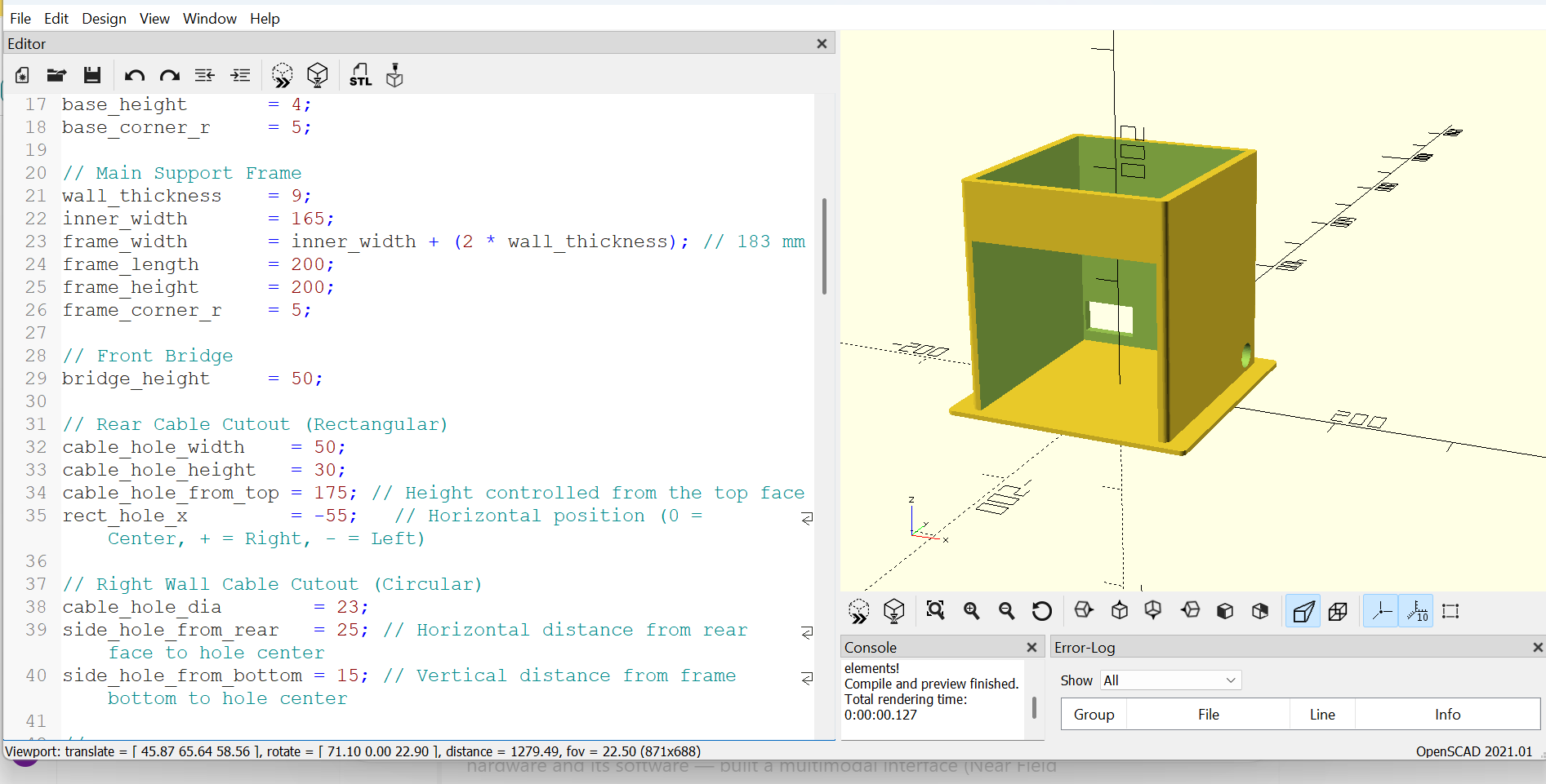
Given the constraint, the AI agent didn't just shrink the kiosk — it split it into four interlocking sections, each sized to fit the printer, and modeled the whole thing as parametric code in OpenSCAD, an open-source CAD tool where every dimension is a variable an AI can read, reason about and adjust.
Wall thickness, inner cavity size, corner radii, a VESA-75 mounting pattern for the screen, a QR-scanner housing, press-fit joints with built-in tolerance — every one of those was a named parameter the agent could tune, not a shape drawn by hand.
From Tooling Quote to Working Part
The same enclosure, built two different ways. One depends on tooling and volume. The other depends on a prompt and a printer.
| What Matters | Traditional Manufacturing | AI-Generated & 3D-Printed |
|---|---|---|
| Time to first physical part | ✗8–12 weeks of tooling and production | ✓Under 24 hours from design to printed part |
| Upfront tooling cost | ✗$5,000–$50,000+ in molds and fixtures | ✓$0 — no molds, no tooling |
| Design changes | ✗Requires new tooling and weeks of delay | ✓Edit a parameter, reprint the same day |
| Minimum viable order | ✗Hundreds to thousands of units | ✓Economical at a single unit |
| Enclosure design origin | ✗Manually modeled by a CAD engineer | ✓AI-assisted parametric design in OpenSCAD |
| Assembly & repair | ✗Bonded or welded — hard to service | ✓Snap-fit modular parts — field-serviceable |
From a Prompt to a Physical Kiosk
Four stages, no factory. Everything that used to require tooling, machinists and a supply chain happened at a desk and a desktop printer.
DESIGN
An AI agent modeled a parametric, four-part kiosk enclosure in OpenSCAD.
Each shell is printed in carbon-fiber-reinforced filament, one part per print job.
ASSEMBLE
The four parts snap together like building blocks — no glue, no fasteners.
DEPLOY
The enclosure becomes a real, running kiosk with screen, printer and scanner installed.
Step 1 — AI-Assisted Parametric Design
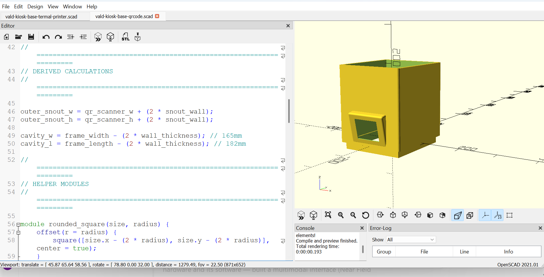
QR-Scanner Module
The QR-code scanner housing — a swappable "snout" module designed as its own OpenSCAD file.
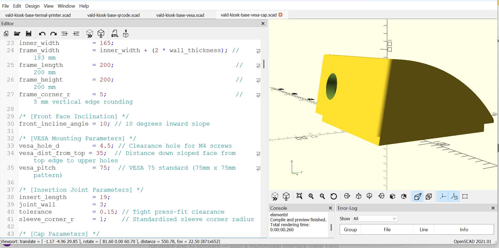
Sloped Mounting Cap
The upper cap section, with a 10° inward slope and press-fit joint geometry generated from parameters.
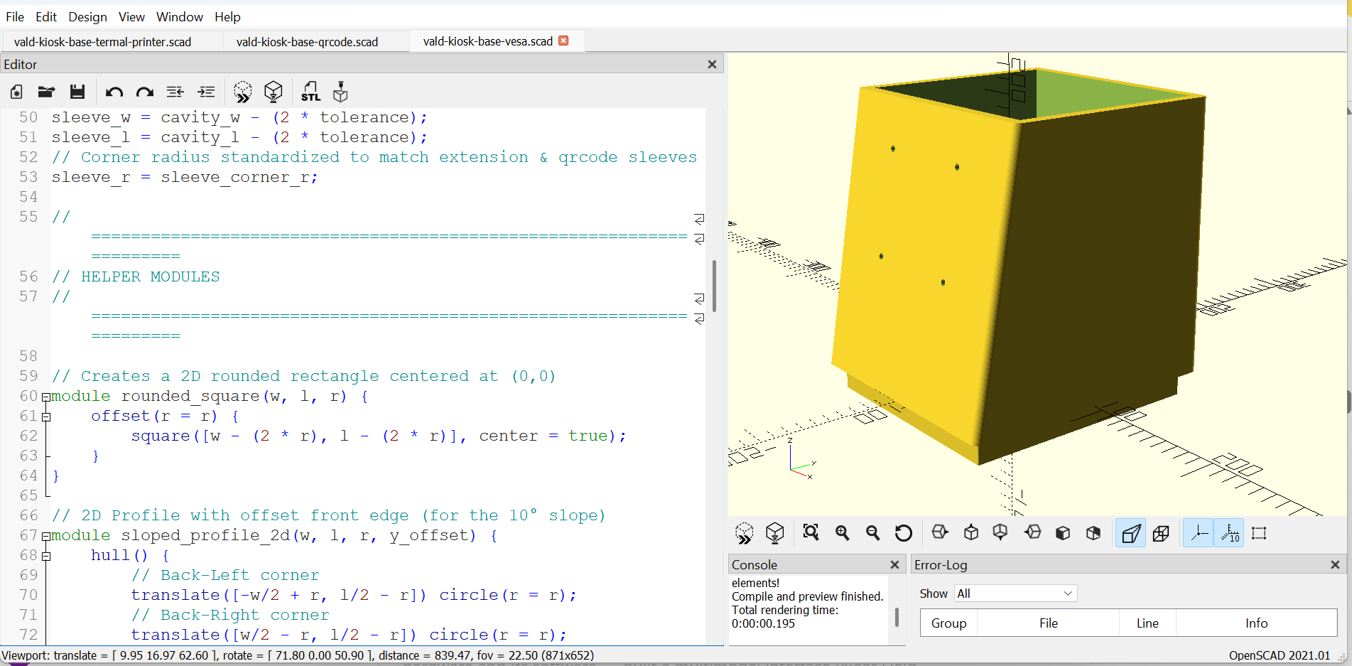
VESA-75 Mounting Shell
The main shell, with four M4 clearance holes on a standard 75×75 mm VESA pattern for the display.
Step 2 — Carbon-Fiber Multi-Material Printing
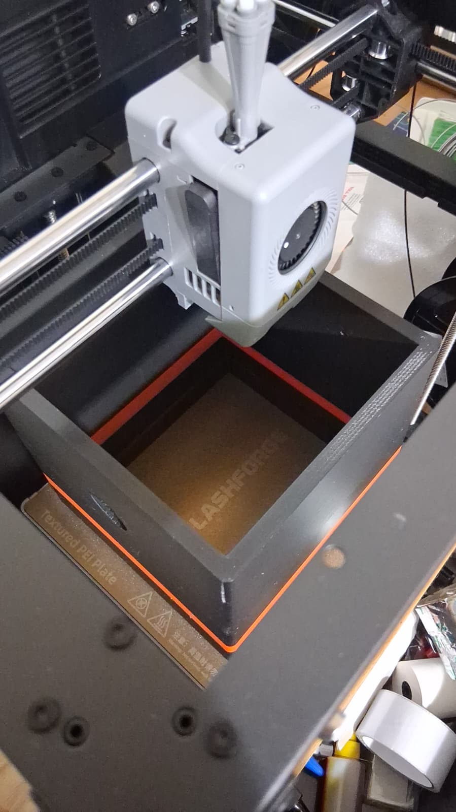
First Layers
A shell begins printing on a textured PEI plate, inside the printer's enclosed chamber.
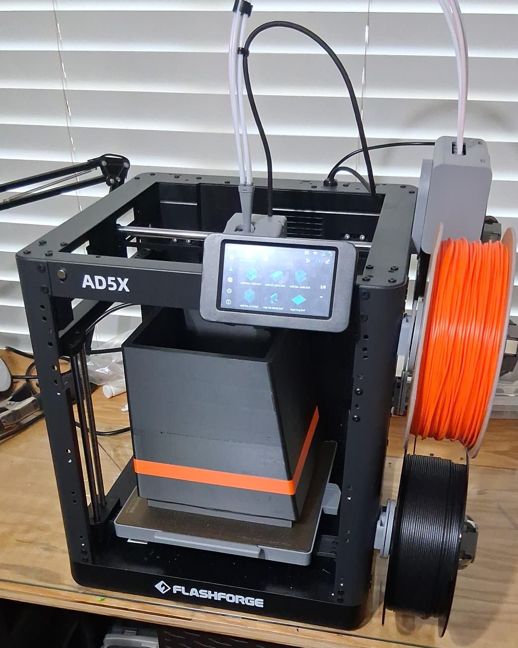
The Printer
A FlashForge AD5X multi-material printer, loaded with carbon-fiber-reinforced filament, mid-job.
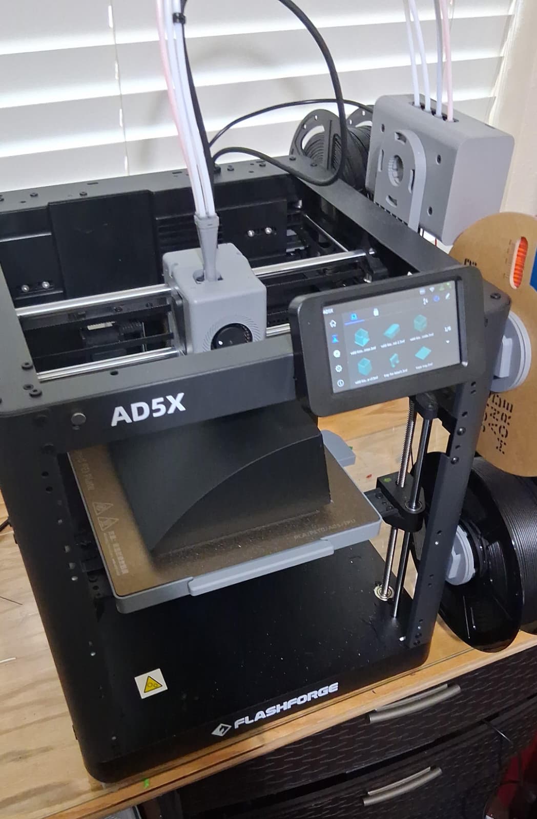
One Part at a Time
Each of the four sections is printed separately, sized to fit inside the 22 cm build volume.
Step 3 — Snap-Fit Assembly, Like LEGO
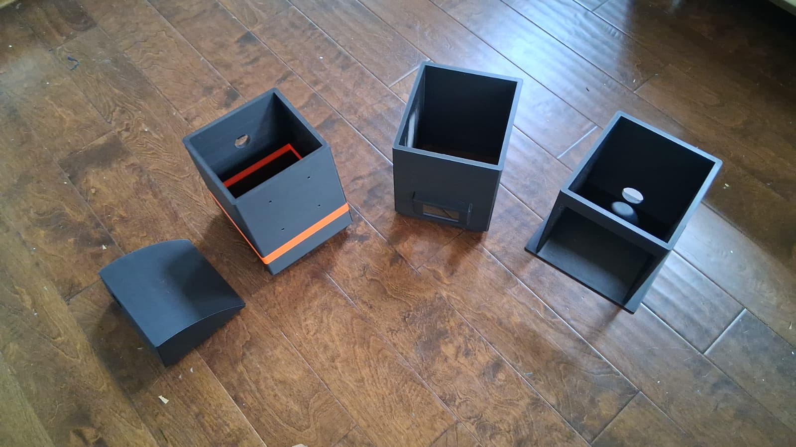
Four Parts, Laid Out
Base, mid shell, upper shell and cap — every printed section, before assembly, matched to the parametric design.
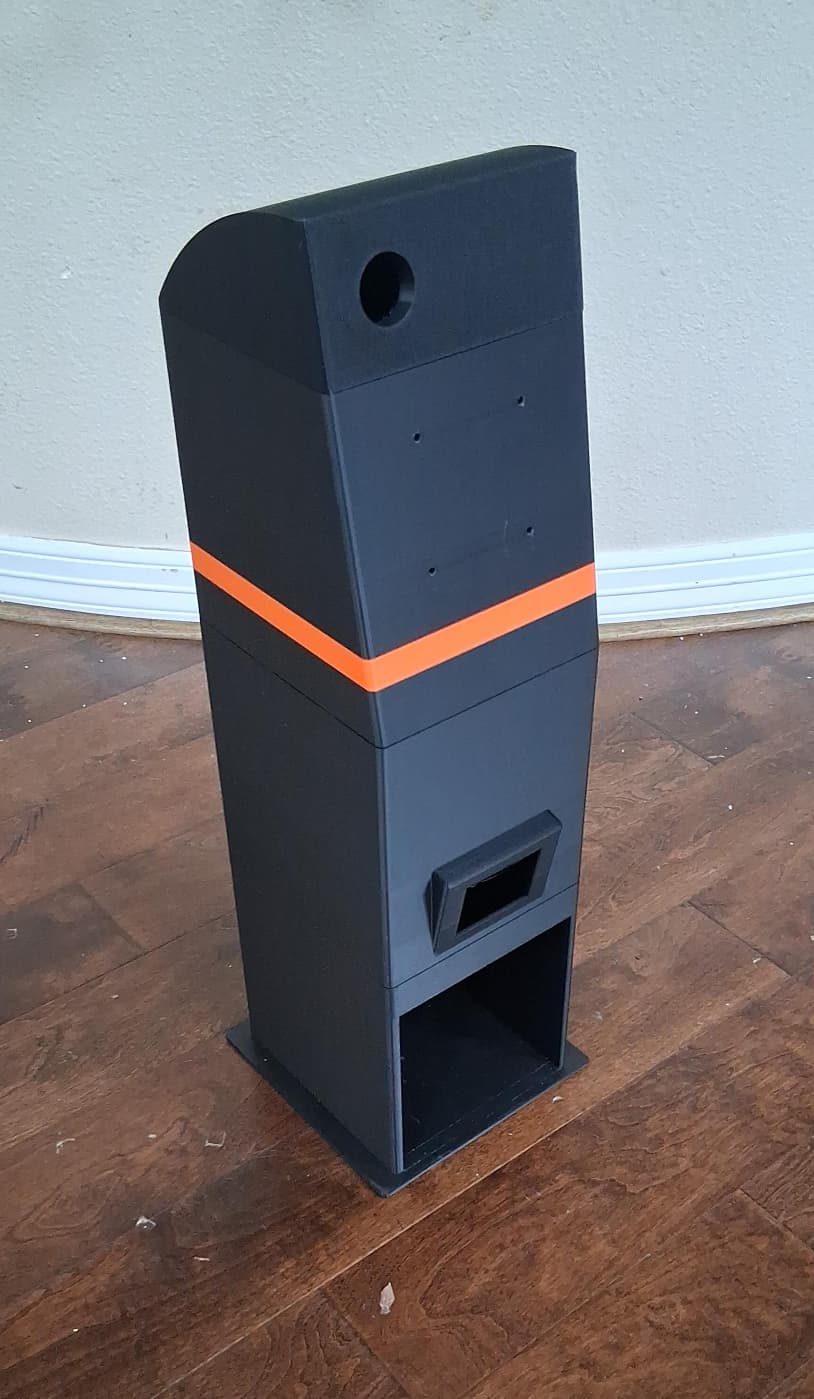
One Finished Enclosure
The same four parts, snapped together with the press-fit joints and tolerances built into the design — no adhesive.
Step 4 — A Functional Kiosk, Deployed
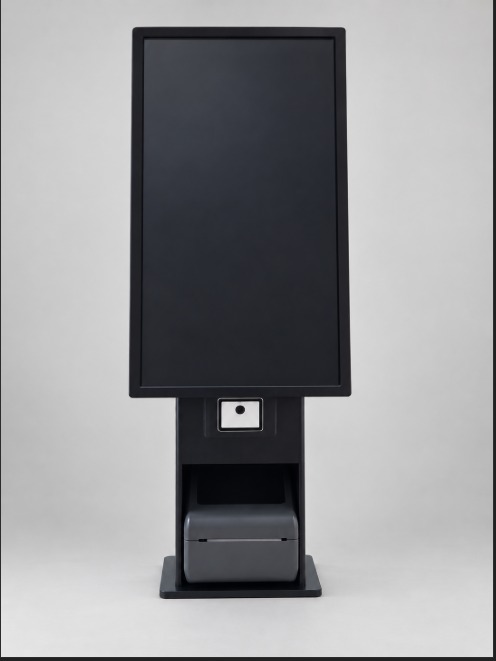
The finished kiosk in its first real environment.
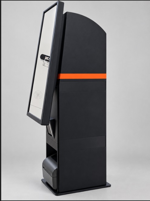
The fully assembled enclosure, free-standing.
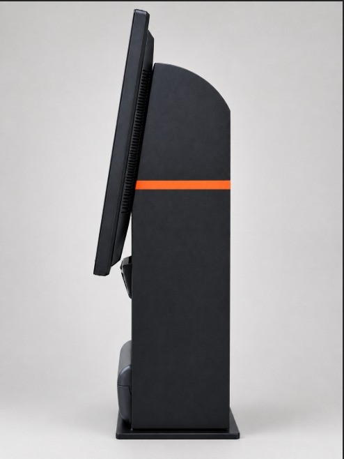
Side profile — the sloped face and camera housing.
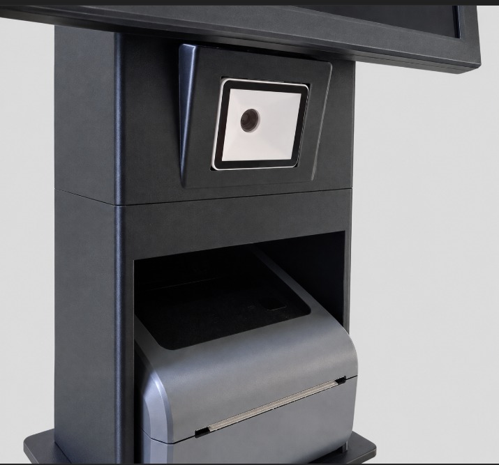
Close-up of the QR-scanner window and printer bay.
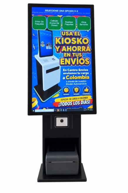
Running real self-service software, days after the first prompt.
What Autonomous Fabrication Makes Possible
This project proves a working pipeline: natural-language intent becomes AI-generated parametric CAD, which becomes a sliced print job, which becomes a real, physical part — with no human machinist and no CAD engineer drawing shapes by hand. Days, not months. Single-unit economics, not minimum order quantities.
For LogiKiosk, that pipeline is a preview of how kiosk hardware itself can evolve: the same modular, parametric base reshaped in minutes for a different vertical — a QR-scanner snout for Self Shipping, a key-encoder bay for AI Hotel — by adjusting parameters instead of commissioning new tooling. Replacement parts printed near the point of deployment instead of shipped across the world. Hardware that iterates at the same pace as the AI agents already running inside every kiosk.
One Prototype. Two Perspectives.
This kiosk proves something about the process, and it points toward something bigger about the future of kiosk hardware. AI 3D Fabrication answers both.
An AI-to-Object Pipeline That Works
Kiosks Designed and Built On Demand
AI-Generated Parametric CAD
Multi-Material Carbon Fiber Printing
Snap-Fit Modular Assembly
22×22×22 cm Build Volume, Engineered Around
Zero Tooling, Zero Minimum Order
Field-Repairable by Design
VESA-75 Mount Compatible
A Blueprint for Autonomous Fabrication
FROM PROMPT TO PRODUCT.
Design. Print. Assemble. Deploy.

Building the Hardware Behind the AI
This is what LogiKiosk's AI-directed design and fabrication pipeline looks like today. Let us walk you through what it could mean for the next kiosk your network needs.
Request a Demo (239) 451-6077